A hacker's journey: freeing a phone from the ground up, second part
Written by Paul Kocialkowski no commentsWhile I got this LG Optimus Black (P970) phone thinking it would just be another mainstream device to port Replicant to, with the usual flaws of those devices, it already caught my attention more than any other phone I stumbled upon in quite some time. Having a GP device meant that the bootrom would allow me to run any code I want as first bootloader: this opens up the way of having a free bootloader running on that device. To this day, only the GTA04 has Replicant support and a free bootloader, so having a second device alike would be a huge step forward for freedom, especially since it is still very common and easy to find second hand.
Loading a bootloader

Boot order resistorsAll of this felt really great, but I still needed a way to load code for developing a free bootloader. The stock bootloader is installed in MMC2, which is the first boot medium. Boot order is defined by pull-up and pull-down resistors attached to some pins of the SoC and thanks to the extensive documentation I had in hands regarding both the phone and the SoC, I was easily able to figure out how it works (not to mention that it's exactly the same thing as the GTA04). After identifying which resistors were actually in place on the board (the schematics shows some resistors that may or may not be present), it struck me while looking closely at it that I was literally one resistor away from having USB boot first and MMC2 boot second.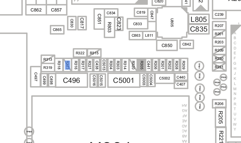
One resistor awayThis is an ideal situation as it allows to boot code from USB and would still leave the device usable to boot the default system after the USB timeout expires. Even though I didn't have a very the best soldering iron around at the time, I was so excited that I decided to go with a general-purpose iron and thanks to a bit a practice, I was able to remove the tiny tiny resistor without doing any harm to the rest of the device. I just plugged the phone in with no battery and started jumping around as this showed up on dmesg:
usb 3-4: new high-speed USB device number 9 using xhci_hcd
usb 3-4: unable to get BOS descriptor
usb 3-4: New USB device found, idVendor=0451, idProduct=d00e
usb 3-4: New USB device strings: Mfr=33, Product=37, SerialNumber=0
usb 3-4: Product: OMAP3630
usb 3-4: Manufacturer: Texas Instruments
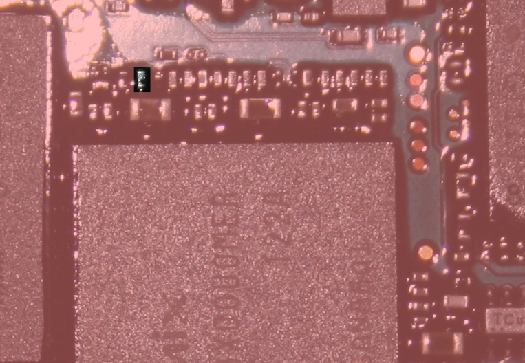
Tiny tiny resistorIndicating that the bootrom had booted from USB first. Another approach to all this would have been to write the boot order to a particular register from the running system in order to tell the bootrom to boot from USB first, but this would have introduced a longer development overhead and taken all the fun out of it! A set of convenient tools that is well known to people working on OMAP bootloaders quickly enabled me to converse with the bootrom, as described in the TRM. Eventually, I was able to upload the stock X-Loader build via USB and get it to boot the system that way.
Seeing the light
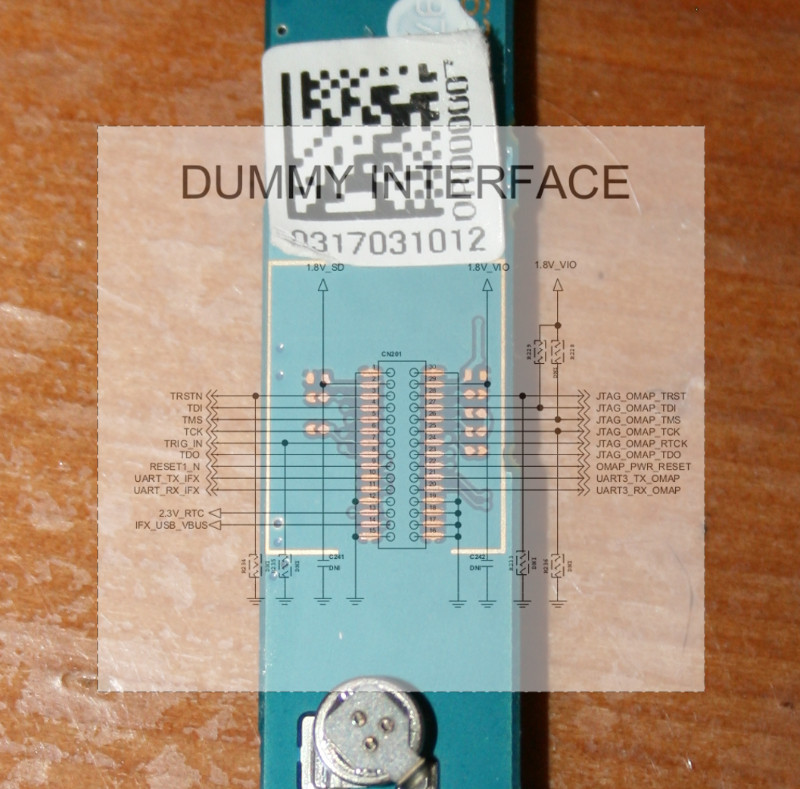
DUMMY INTERFACENevertheless, I was still blind. Being able to run code is one thing, but debugging a whole bootloader is another much more complex one. Mostly, I needed a way to get serial output from the code I would submit. The usual way to do this is to use UART I/O. On the OMAP3, UART3 is usually reserved for that purpose: I wasn't so surprised when I found that UART3 connectors were exported on pads at the back of the device (under a sticker). Sadly, those pads were not very easy to access, nor were they big enough to allow for easy soldering. Feeling adventurous, I decided to give it a try with my messy soldering iron and while I got a tiny wire to hold in place for a moment, it eventually ended up in tearing the pad off the board, making any further soldering there impossible. That was a big turn off but instead of giving up, I looked for other ways to get UART3. There was only one option left, soldering on the pads of the UART switch module. Again, it was some very precise work there and I failed again, leaving a mess out of the connectors. The phone still booted, but I lost all my chances of debugging bootloader code on it.
A glimpse of hope
That's when I recalled meeting a member of one of the local free software groups at an install party, a few months back who had told me about the same device that he bricked. With all the information I had in hand, it was hard to believe such a device could actually be bricked, so I got in touch with him, explained the situation and as it turns out the non-functional device was still sitting around in a drawer, I quickly bought his “bricked” device at a fair price. With a new device in hands, the adventure could resume where it was so abruptly suspended. To do things right, I decided to forget about my own unadapted soldering iron and do the soldering at the local hackerspace, the LabX. While I'm sadly not a member nor a frequent visitor of the LabX (mostly because schoolwork takes most of my week evenings), I knew some of the people there and was very happy to see that, as usual in our community, many were happy to help and give me hints on how to do this right. Despite all that good intention, the dumbest thing happened. The very afternoon before I planned to get the soldering done, I plugged the phone to a wall charger and left it there for a while. When I returned to it, it was incredibly hot and wouldn't turn on again, which got me worried. Nevertheless, I packed it and moved to LabX, where it didn't show any sign of improvement. Still, I decided to go through with the soldering, as it would be good practice anyway. I got both the resistor removal and the UART pad soldering right, but the device still wouldn't work. After some investigation, it turned out that the battery V+ and GND signals were shorted, perhaps as a result of a melted component I couldn't locate. I was never able to get that device to turn on again.
Happily ever after
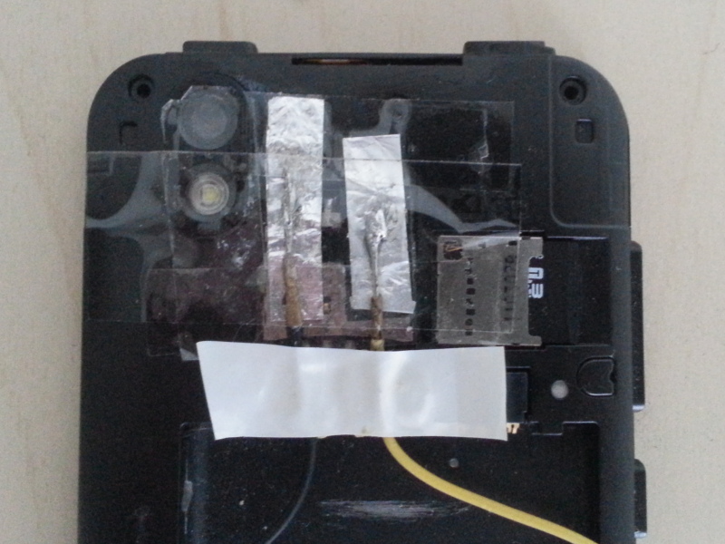
UART3 Tx and GND padsBack to the same situation I was a while ago, with no suitable device for development. Since I just couldn't give up after all the progress that was made, I bought yet another device second hand and went back to LabX for another session of intense soldering. The resistor removal went well, but we got the UART pad teared off the board again. I then headed for the backup solution, the UART switch, which succeeded thanks to the precise tools I had at disposal. The same evening, I was able to get the stock bootloader's debug output! After a bit of thinking and tinkering, I ended up with two nice pads made out of aluminium foil for the OMAP3 UART3's TX and GND. I didn't want to risk going as far as getting the RX signal out there, as it felt too much of an unnecessary risk (debug output is fairly sufficient for debugging).
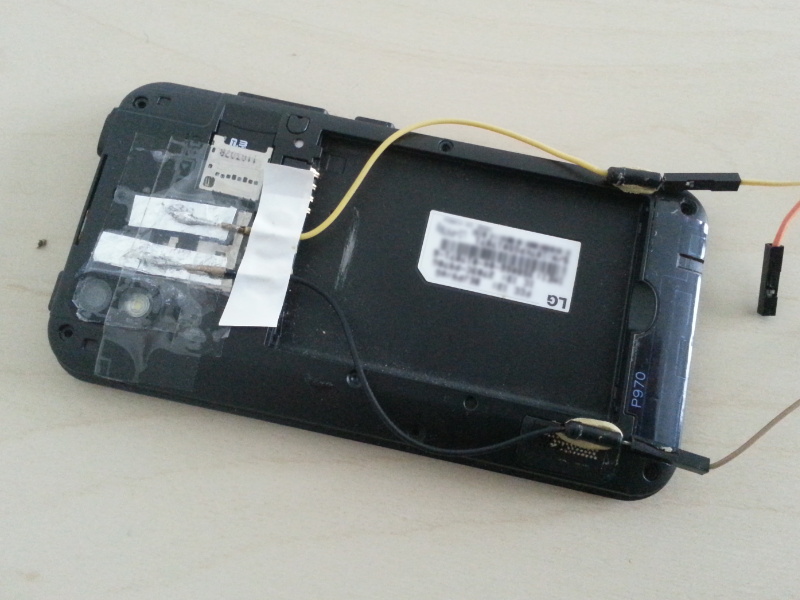
The LG Optimus Black (P970) with UART exposed
This post is part of a series of articles about freeing the LG Optimus Black (P970):