This year's edition of RMLL/LSM, the free software conference that travels in and out of France (with an international aim) just ended. Time to take a step back and look at what happened during the 4/5 days I was there.
Thankfully, I get to travel to such conferences using money from the Replicant fund, so I will be refunded both my train tickets and my stay this time again. It makes it much easier (and to be honest, possible at all) for me to attend such conferences. This way, I don't have to worry about finding a summer job and can instead focus on what I do best, reverse engineering proprietary stuff and writing (free) replacement code.
Monday
This time, I arrived on Monday afternoon and could attend a first talk after a quick chat with the lovely people from the information booth. The talk, that was part of the security track, was presented by Lunar (Tor and Debian developer) and reported the current state of the art of reproducible builds for Debian (and more). It was really nice to see such overwhelming progress accomplished, after I attended the initial talk during which he announced the reproducible builds initiative a year and a half back, at FOSDEM. Lunar's talk answered most of the questions I had regarding how to make software reproducible. I am especially interested in making the U-Boot bootloader reproducible. I had that idea at the back of my head for some time now and decided to jump in after seeing a contribution in that direction on the U-Boot mailing list. Eventually, we managed to get some of that work done (right) later in the week. The rest of the afternoon was filled with chatting around in the village. In the evening, I met people from the event at a local bar, were free music was being played. It was a nice atmosphere and we had some interesting technical discussions (and let's be honest, many trolls as well)! I was thrilled to see that people were not only aware of Replicant, but also had a lot of interest in it.
Tuesday
On Tuesday, it was time to get to the workshop I was supposed to co-host. The whole day was filled with various activities around different kinds of embedded devices (some were about scientific measurements, some about Arduino, etc). In addition, most of these were built with education in mind. When the first one ended, it was time for me to leave in order to reach the room where I was to present my first talk. The video recording seemed to be done right and hopefully, the video of the whole thing will be available eventually. Not that many people showed up, but the ones that were there seemed really interested. I got to meet and talk with a few people after my presentation, some of whom decided to come to RMLL only to have a chat with me. What a surprise! The afternoon went on and I attended a few talks, including a round table around the concept of civilian re-appropriation. It was presented by Veronique Bonnet, who's a philosopher and a member of April, one of the French associations that take a stand for freedom on digital devices (and actually get it right). Richard Stallman (RMS) was also there, even though he apparently didn't quite understand the wording of the subject in French. Still, some interesting things were said and RMS displayed his usual sense of humour here and there, sometimes making the audience burst into laughter. Once it was over, we got to chat a bit, in a very friendly environment, which was very nice. A free music concert was organized near the event, so a few youngsters (including myself) decided to go before calling it a day.
Wednesday
Wednesday was the occasion for me to be around the workshop more often, but very few people showed up because it was missing from the printed schedule, something I only came around to realize once it was too late, a week before the event or so. Despite some paper indications and the addition of the workshop to the online program, the place remained rather quiet, which wasn't so much of a problem given my aggravating state of sleep deprivation. Before lunch, I gave my other talk about Replicant, a longer and much more technical one. To my surprise, many more people showed up (perhaps the result of meeting a few people during the first few days). The talk itself went well and everything fit on schedule. For the record, the content of both talks (which summed up to 1 hour and 40 minutes, mostly excluding questions) was what I had planned on delivering during my (50-minute long) talk at FOSDEM this year: no wonder I had to stop half-way back then! Afterwards, I was lucky to get help for making U-Boot reproducible from Lunar, whose efficiency, vivacity and kindness really made the task painless. There are still bits and pieces to bring together to craft a proper patch, but I'll get around doing it sooner or later. After alternating between the workshop and talking to great people at the village, I ended up meeting back lots of interesting people at a Harry Potter-themed bar, le Chaudron Baveur (not that the owner deserves any particular good word about it, given that he wasn't exactly pleasant).
Thursday
The next day went on pretty much similarly, except that I had no talk left to give, and thus no particular pressure or place to be at (except for the workshop, that remained desperately empty). Just like any other day at RMLL, I met tons of incredible people and had lots of interesting talks. In the afternoon, the main “political” event of the week took place, with a round table regarding interoperability and DRMs. The speakers were a high-ranking official from HADOPI and Marie Duponchelle, who conducted a thesis on the very subject. Overall, it was very strange, mostly because the nature of the debate soon revealed to be astonishingly stupid and a pure waste of time. The main question was how to allow the entertainment industry to use DRMs while maintaining interoperability. The answer is plain and simple: it can't be done. Despite that very clear statement, that was introduced eventually by Marie Duponchelle (in spite of the situation Videolan was in), the debate went on and the HADOPI representative produced vague statements with apparently no ties to the technical reality one after the other. At some point, the audience got pissed off and started expressing our community's point of view in very clear ways, such as encouraging everyone to share culture in the most efficient ways: torrent, VPNs and Tor. All that followed by rounds of applause, naturally. More serious questions were raised, such as the existence of public domain in practice when only copies of an piece of art exist with DRMs. The HADOPI representative answered that any piece of art is itself distinct from the media it is distributed on, which may be a fair point, but doesn't solve anything. She also suggested that the BNF could receive non-protected copies of it, but this is neither its mission nor a reliable solution for people who will find a DRM-tainted copy decades later, unable to read it despite the fact it is in public domain. The talk ended with François Revol (Haiku developer) handing over a big coin of 1 Hadopi to the representative, a way to show our community's support for this organism at a time of budget cuts. Bottomline: this was purely a waste a time (despite providing some form of entertainment). No wonder some decided to master the fine art of origami during the talk instead of listening to that whole mess. Hopefully, the main political talk will prove to be more interesting next year. In any case, it probably cannot sink much lower. Later that day was the repas du libre, the traditional classy-ish dinner where we all meet together and look back at the week (everybody knows Friday is mostly for getting over the hangover induced by the previous night's drinking and also for packing). I didn't plan on attending at first, since the food wasn't really worth it last year, but changed my mind given some pretty solid arguments. Or maybe just pretty at all. In any case, I got to formally meet Benjamin Bayart (some fine blood forensics can probably assess for that) who not only showed interest in Replicant (and other things I'm doing these days) but offered me his help in every way possible. That evening is probably the time I had the most fun at RMLL, thanks to Benjamin, Fabien, Frédéric, jfefe and plenty others. Kudos to them for their support in times of great needs, that was a relief. Thankfully, my LG Optimus Black (P970) booted just fine, so in the end, it's fair to say that the various issues encountered were accounted for and that the whole thing provided a working result, that will certainly become a base for future developments, now that the initial trouble is behind us.
Friday
Friday was a bit less fun than the other days, in part for reasons of a physical nature. I still managed to reach the event in time to be reminded that Trinity does use nmap and it's fair to say that it's the coolest thing. Sadly, some people had to leave early and I couldn't conclude some of the ongoing arguments that had developed throughout the week. Hopefully, there will be other occasions to meet (and certainly closer than Beauvais), but that's ultimately not really up to me, despite my best intentions.
That whole I2C issue took me close to two months to resolve. As I recall, probing finally worked on my last day of summer vacation. I was so happy to finally have figured the issue out, that over the next week or so, I cleaned-up the X-Loader code and got it to a state where it could load LK (the only working second-stage bootloader binary I had at disposal) from the external sdcard.
U-Boot
A few months went by, I started working on other things, like Allwinner devices, on my ever-shrinking amount of spare time. At some point, I decided I needed to get back to it and properly port U-Boot. Of course, we're talking about upstream U-Boot here, as I'm not a big fan of either fighting with the code LG released (that is old, poorly written and contains a lot of dead code) or adapting versions of U-Boot code coming from TI. Working with upstream has countless advantages, among which I see an opportunity to get familiar with the current state of the U-Boot code as well as going through the process of having my code reviewed by peers, which is always a very enriching experience. It ensures that code is written the right way, fits well in the overall design and doesn't break something else. The temptation of doing easy and nasty changes to suit our case better is big when working on our own personal fork of such a big project and that's exactly what I wanted to avoid. Finally, having the phone in my pocked supported by upstream is pretty cool, right?
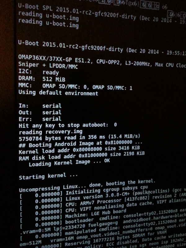
As I first dig into the U-Boot code, it struck me that an increasing number of devices are using the U-Boot SPL as a first stage loader. The U-Boot SPL is a minimalistic build of U-Boot that only contains the minimal amount of code to be able to chainload the usual and complete U-Boot binary. There is SPL support for the OMAP3, so I thought I might as well give it a try, since X-Loader is an old copy of deprecated U-Boot code anyways. It didn't take me long to get it to run, with the usual base address correction due to the fact that I'm using peripheral booting. I will most certainly drop X-Loader and go with U-Boot and the U-Boot SPL for the future.
Current status and overlook of the future
U-Boot runningTo this day, I have submitted a handful of patches upstream to add support for various features that I need for the P970 (named sniper in the code) and most of those were accepted already. The rest of it is available on my personal git repository for the Optimus Black (P970) codename sniper's U-Boot port. I am still working on getting board support ready with a certain amount of features, like fastboot support (including eMMC flashing) and being able to get the SPL to boot U-Boot from the external sdcard on demand, to allow failsafe U-Boot development without having to unsolder a resistor. A few others things are needed in order to be able to load and run kernels painlessly: currently, booting Linux is working but a few features appear to be broken.
The next steps in this journey are the following: getting board support ready and accepted in upstream U-Boot and then starting the Replicant port. It shouldn't be too much work to get Replicant running on the device, so I'm confident it will come around. Of course, I will properly document the device on the Replicant wiki at some point in the near future. I am also hoping to talk about this device at FOSDEM this year, among other exciting new things that I've been doing recently.
And once upstream U-Boot support is merged, why stop there? I could just as well try and get some Linux support for it upstream: that could be an interesting and challenging task, despite not being crucial for software freedom. And of course, once everything is properly documented, everyone is welcome to join in and help!
Finally, during all this, I've come to learn about a few other mainstream OMAP GP devices (that I will also document at some point), such as the first generation Kindle Fire from Amazon, which is really likely to become my next target for Replicant after the Optimus Black. Thanks to the great work already achieved by developer Hashcode, there is already an U-Boot port available, and instructions on how to get UART from the device are also available!
Conclusion
Overall, I'm definitely very happy with the way this whole experience went. It most certainly brought me a lot regarding how low-level initialization and bootloaders work and hopefully offered me a chance to make a real difference for those of us who care about having free bootloaders running on the devices in our pockets, in addition to a free system. The odds also seem to be in our favor when it comes to modem isolation, so the whole device is pretty close to being “as good as it gets” today. To be fair, everything is not exactly great about it: graphics acceleration and 3D will still be proprietary, the GPS protocol is still unknown and the video decoding unit (DSP) as well as Wi-Fi and bluetooth require loaded proprietary firmwares.
As a final word, I'd like to thank whoever decided to go with the GP version of the OMAP3630 at LG. Heck, that decision brought me the hell of a ride!
This post is part of a series of articles about freeing the LG Optimus Black (P970):
With all that soldering successfully performed on my LG Optimus Black (P970), I was finally able to load my own code and actually see the results, on UART.
Building and running
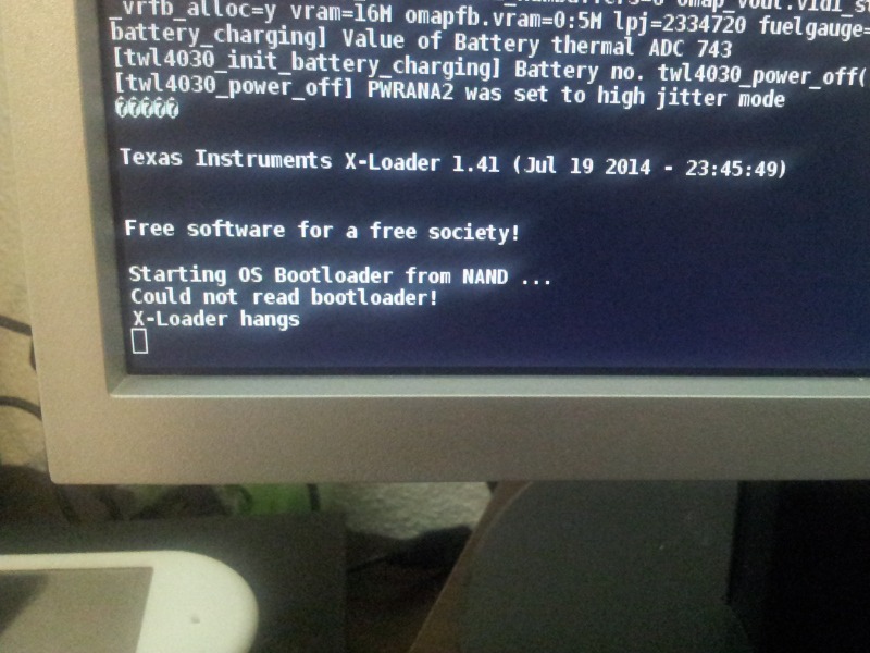
X-LoaderI first tried to build the X-Loader source code that was released by LG and, after addressing some relocation issues, got it to finally print something on serial! The first step was to get X-Loader to run on the device, to a point where it could load and run U-Boot. I had at disposal the version released by LG, which is not exactly the most recent one out there, and found various other versions on the Internet. Overall, I was told that X-Loader development is a bit of a mess: it was initiated by TI for OMAP devices, but there is no clear notion of upstream for it, just different branches that work on different OMAP devices. The closest thing I could find was the X-Loader project on Gitorious, which was an initiative to gather all the various X-Loader trees into one, as I was told. That felt like the right path to follow, so I decided to use it as a base for development for the Optimus Black (P970) codename sniper's X-Loader port. Most things worked nicely by importing code from the LG release, even RAM initialization was rather painless and worked straight away. Soon enough, I was at a point where my concern was loading and running the next stage bootloader: U-Boot.
Loading the next stage
The Optimus Black (P970)'s internal storage is eMMC. There is a partition for X-Loader and one for U-Boot too. As I wanted to keep the devices in an usable state (a working shell on a kernel that actually works can turn out to be an important resource when working close to hardware), I decided to avoid flashing the internal memory. And flashing requires the current system to work, so that would only have worked once. Not really a possibility. Of course, I would still need to be able to boot from internal memory for production, once everything is known to work. Internal storage is connected to the OMAP3's MMC2 controller while the external sdcard is connected to MMC1. The current X-Loader code would only deal with MMC1, so I decided to give booting from internal memory a shot. After all, there was already a bootloader in there (LK) and my X-Loader code should have been able to boot it as well. Given that the bootrom has to be able to boot directly from MMC2 (it is the first boot option), everything is wired according to the TRM: that is, using the appropriate TWL5030 regulators. Thanks to that, the code in X-Loader was able to use the eMMC without any change and it would soon load and run the preinstalled LK.
Booting from the external sdcard
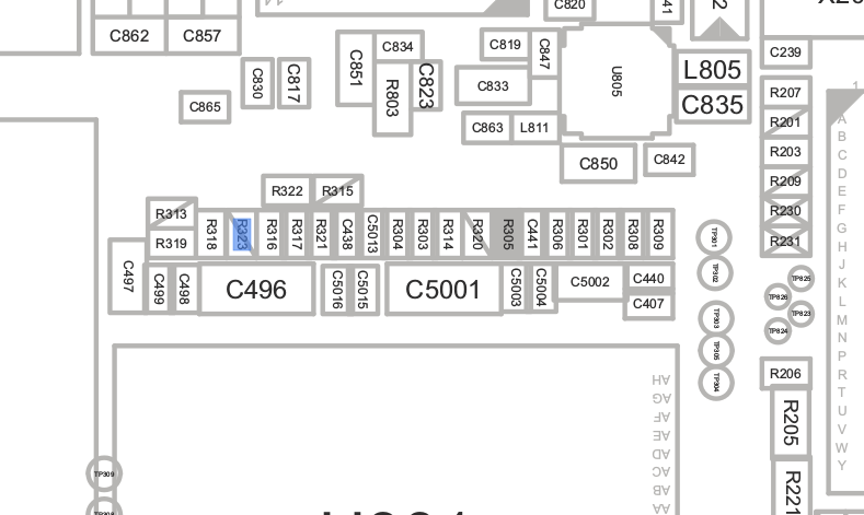
Real trouble began when I started looking into getting X-Loader to read from MMC1 (the external sdcard). Modifying X-Loader so that it would also allow booting from MMC1 wasn't enough to do the trick. As it turned out, MMC1 is powered by an external PMIC, the LP8720: one of its LDOs is dedicated to powering MMC1 (3.0V_MMC). Looking at the schematics, it appeared that the LP8720 is contacted through I2C3. Thankfully, it had good enough documentation available (in addition to the reference code from LG), so it was really easy to figure out how it works.
X-Loader's I2C code wasn't designed to allow changing the bus either, so I had to implement that too. With the bus switched to I2C3, I should have been able to communicate with the device. Except that it didn't work. I spent a crazy amount of time looking at the TRM, making sure that every necessary clock was enabled, every needed pin muxed properly, but it didn't do. The controller would only return the same error. Nevertheless, it worked perfectly on the preinstalled Android version and other buses were working normally too. It just didn't seem to make sense and after a week or so, this got me very frustrated.
Frustration and investigation
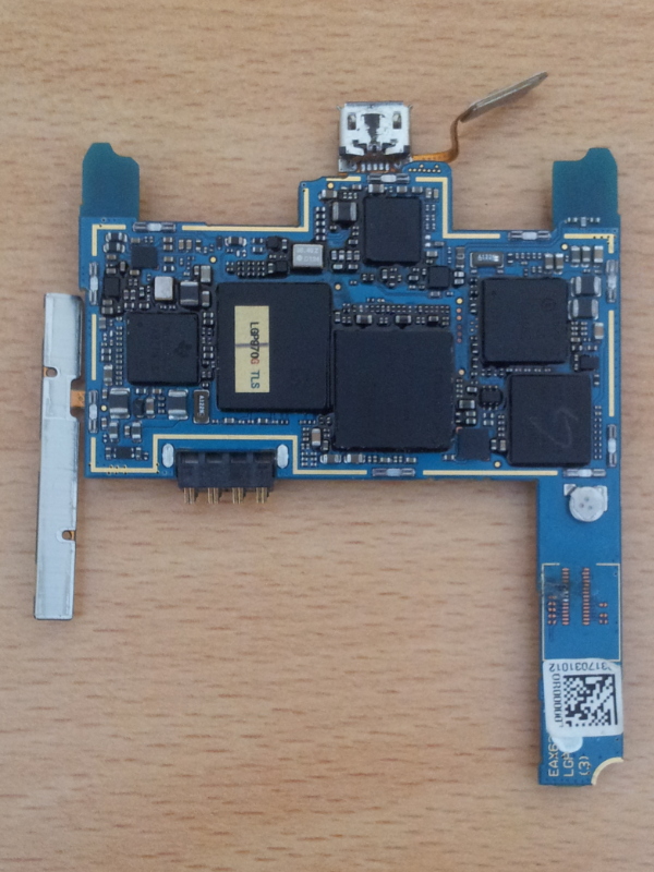
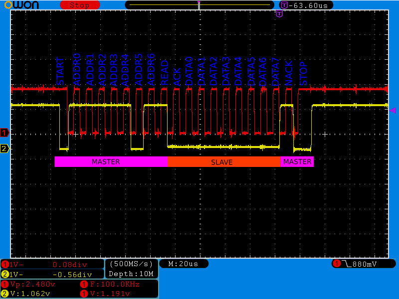
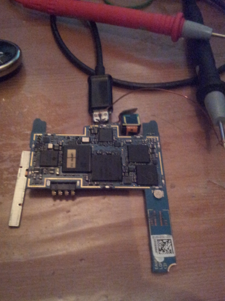
Spare boardAt some point, I even wrote an I2C probe function from scratch based on what the TRM recommends, with no better result than the original code. Looking at it more closely, it seemed that the controller wasn't getting any NACK. I was able to reproduce the same behavior by disabling input on another I2C bus, or by muxing the pins to GPIO. Still, it didn't make sense that it happened all the time on I2C3, so I asked on the TI E2E community forums but didn't really get a clue there. Since I had another working device at disposal, I decided to tear its board off, keep only the USB connector, load my code and look with a probe at what was actually going on on the bus. Lacking proper hardware, I used my buspirate as a logic analyzer but it didn't really work out, neither did my Arduino Uno. It was also particularly hard as I had to probe on two very tiny resistors to get I2C3's SCL and SDA lines. I decided to head back to LabX, where I knew that people would have a clue about how to do this properly. It turned out that nouveau developer Martin Peres was around at that time and kindly offered to bring his own digital oscilloscope. That was really a life saver! After a short while, we were able to probe the SCL and SDA lines and see things actually going on in there. A few times, we were even able to catch a full trace with SDA and SCL simultaneously. Martin knew the I2C protocol well, so we were able to decode the transaction, only to find out that everything was going on just fine. NACK was there and I just couldn't understand why the controller wasn't getting it.
I2C3 trace
GPIO to the rescue!
Probing the spare boardIn the meantime, while I was discussing the issue with fellow developer GNUtoo, he suggested that I mux the pins to GPIO to see what reads. The device with UART attached did show 1 for GPIO read on I2C1 SDA and SCL lines but showed 1 on SDA and 0 on SCL on I2C3. It was as if the SCL line wasn't pulled high as it should have been. I could not actually measure the tension there, as opening up the case would tear off my UART setup. On the spare board, it was clear that SCL was pulled high by reading the voltage, so the 0 GPIO read did seem like the I2C controller on the OMAP wasn't reading the values properly. It still worked normally on Android though, so this was clearly not a hardware problem. That's when I decided to take an extra step: checking that the spare board actually read 0 like the board with UART did. Since the spare board didn't have UART, I needed some other way to read back the values. The most straightforward solution was to use the same I2C3 pins, read the boolean value, then configure the GPIO to output and write back the opposite of the read value (so that I would clearly see the difference).
Sub-board connectedAnd it turned out that reading those values with my voltmeter indicated that the spare board was reading a logical 1 on I2C3 SCL. Thus, my two devices were behaving in two different ways. Moreover, it was likely that I2C3 had been working correctly on the spare board since the very beginning. Now what is the difference between those boards? The most obvious thing is that one is loaded with all the sub PCBs while the other one had only the USB connector attached, which would allow me to probe the I2C3 resistors. Regarding the I2C3 bus, there were indeed a handful of slave devices attached to it on a sub-board that I removed, so I plugged the sub-board back and read the GPIO values again. It then indicated 1 for SDA and 0 for SCL! So the differences between both setups were apparently caused by that sub-board, and something in there was bringing SCL to 0. The slave devices were mostly sensors and looking at the schematics revealed that they were using dedicated regulators. After a quick check, it appeared that 1.8V_MOTION_VIO and 3.0V_MOTION were possibly not enabled. Those are LDOs from the TWL5030, so I just thought I would give a shot at powering them up. Right after that change, the GPIO read on the UART-enabled devices turned to 1 for SCL! Another build to switch the muxing back to the I2C controller and I could finally probe the LP8720 regulator correctly!
This post is part of a series of articles about freeing the LG Optimus Black (P970):
While I got this LG Optimus Black (P970) phone thinking it would just be another mainstream device to port Replicant to, with the usual flaws of those devices, it already caught my attention more than any other phone I stumbled upon in quite some time. Having a GP device meant that the bootrom would allow me to run any code I want as first bootloader: this opens up the way of having a free bootloader running on that device. To this day, only the GTA04 has Replicant support and a free bootloader, so having a second device alike would be a huge step forward for freedom, especially since it is still very common and easy to find second hand.
Loading a bootloader
Boot order resistorsAll of this felt really great, but I still needed a way to load code for developing a free bootloader. The stock bootloader is installed in MMC2, which is the first boot medium. Boot order is defined by pull-up and pull-down resistors attached to some pins of the SoC and thanks to the extensive documentation I had in hands regarding both the phone and the SoC, I was easily able to figure out how it works (not to mention that it's exactly the same thing as the GTA04). After identifying which resistors were actually in place on the board (the schematics shows some resistors that may or may not be present), it struck me while looking closely at it that I was literally one resistor away from having USB boot first and MMC2 boot second. One resistor awayThis is an ideal situation as it allows to boot code from USB and would still leave the device usable to boot the default system after the USB timeout expires. Even though I didn't have a very the best soldering iron around at the time, I was so excited that I decided to go with a general-purpose iron and thanks to a bit a practice, I was able to remove the tiny tiny resistor without doing any harm to the rest of the device. I just plugged the phone in with no battery and started jumping around as this showed up on dmesg:
usb 3-4: new high-speed USB device number 9 using xhci_hcd
usb 3-4: unable to get BOS descriptor
usb 3-4: New USB device found, idVendor=0451, idProduct=d00e
usb 3-4: New USB device strings: Mfr=33, Product=37, SerialNumber=0
usb 3-4: Product: OMAP3630
usb 3-4: Manufacturer: Texas Instruments
Tiny tiny resistorIndicating that the bootrom had booted from USB first. Another approach to all this would have been to write the boot order to a particular register from the running system in order to tell the bootrom to boot from USB first, but this would have introduced a longer development overhead and taken all the fun out of it! A set of convenient tools that is well known to people working on OMAP bootloaders quickly enabled me to converse with the bootrom, as described in the TRM. Eventually, I was able to upload the stock X-Loader build via USB and get it to boot the system that way.
Seeing the light
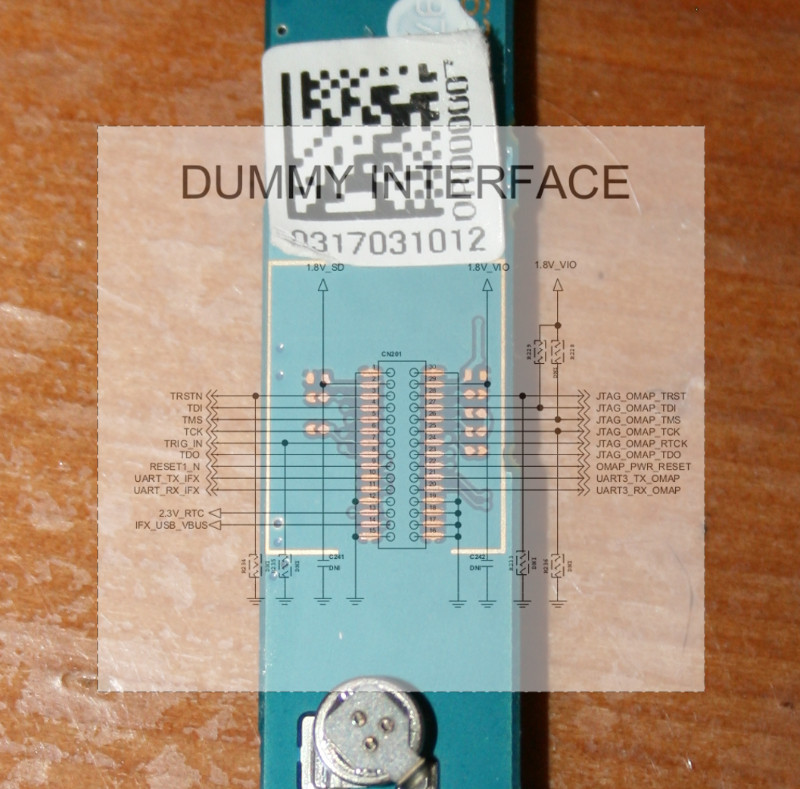
DUMMY INTERFACENevertheless, I was still blind. Being able to run code is one thing, but debugging a whole bootloader is another much more complex one. Mostly, I needed a way to get serial output from the code I would submit. The usual way to do this is to use UART I/O. On the OMAP3, UART3 is usually reserved for that purpose: I wasn't so surprised when I found that UART3 connectors were exported on pads at the back of the device (under a sticker). Sadly, those pads were not very easy to access, nor were they big enough to allow for easy soldering. Feeling adventurous, I decided to give it a try with my messy soldering iron and while I got a tiny wire to hold in place for a moment, it eventually ended up in tearing the pad off the board, making any further soldering there impossible. That was a big turn off but instead of giving up, I looked for other ways to get UART3. There was only one option left, soldering on the pads of the UART switch module. Again, it was some very precise work there and I failed again, leaving a mess out of the connectors. The phone still booted, but I lost all my chances of debugging bootloader code on it.
A glimpse of hope
That's when I recalled meeting a member of one of the local free software groups at an install party, a few months back who had told me about the same device that he bricked. With all the information I had in hand, it was hard to believe such a device could actually be bricked, so I got in touch with him, explained the situation and as it turns out the non-functional device was still sitting around in a drawer, I quickly bought his “bricked” device at a fair price. With a new device in hands, the adventure could resume where it was so abruptly suspended. To do things right, I decided to forget about my own unadapted soldering iron and do the soldering at the local hackerspace, the LabX. While I'm sadly not a member nor a frequent visitor of the LabX (mostly because schoolwork takes most of my week evenings), I knew some of the people there and was very happy to see that, as usual in our community, many were happy to help and give me hints on how to do this right. Despite all that good intention, the dumbest thing happened. The very afternoon before I planned to get the soldering done, I plugged the phone to a wall charger and left it there for a while. When I returned to it, it was incredibly hot and wouldn't turn on again, which got me worried. Nevertheless, I packed it and moved to LabX, where it didn't show any sign of improvement. Still, I decided to go through with the soldering, as it would be good practice anyway. I got both the resistor removal and the UART pad soldering right, but the device still wouldn't work. After some investigation, it turned out that the battery V+ and GND signals were shorted, perhaps as a result of a melted component I couldn't locate. I was never able to get that device to turn on again.
Happily ever after
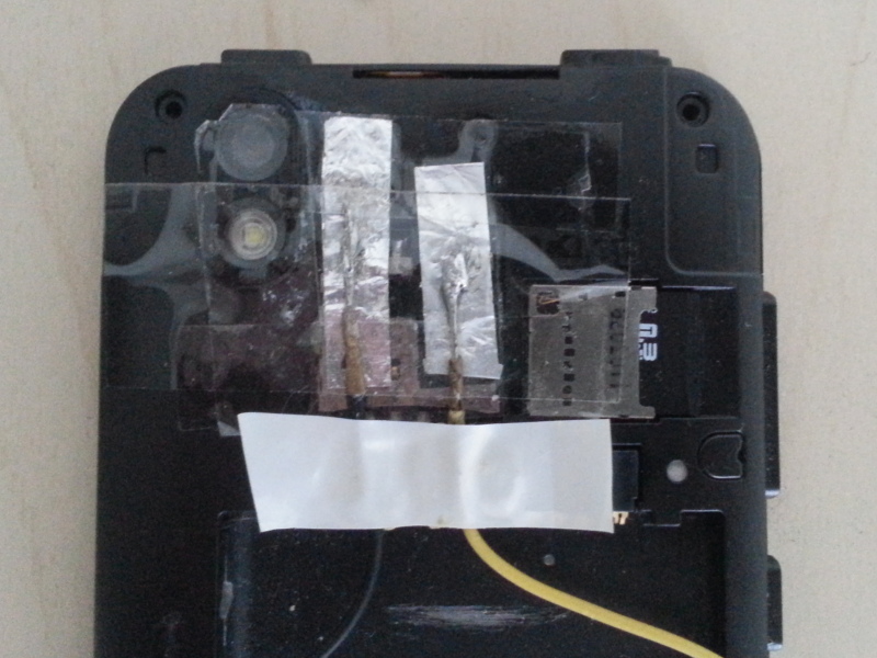
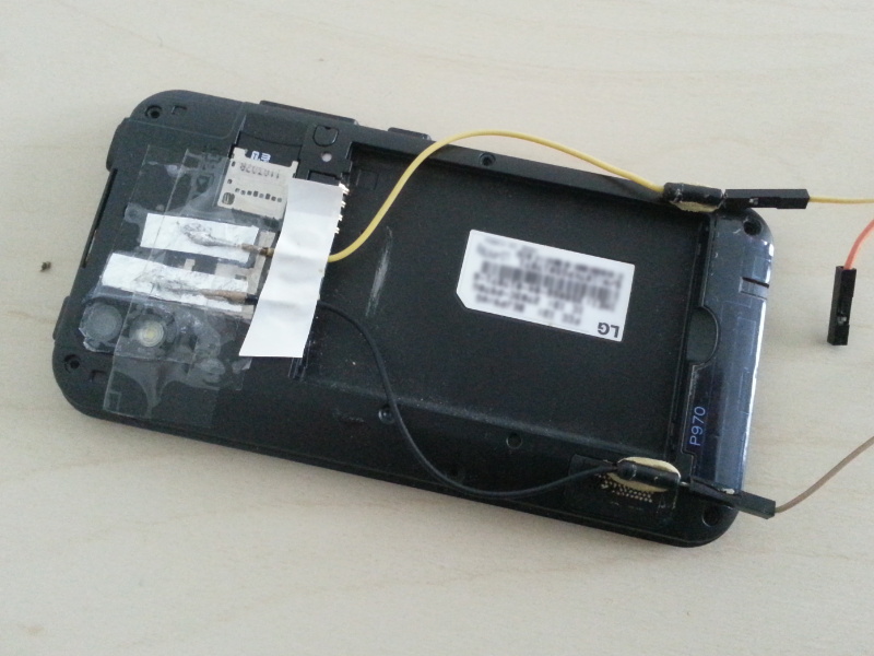
UART3 Tx and GND padsBack to the same situation I was a while ago, with no suitable device for development. Since I just couldn't give up after all the progress that was made, I bought yet another device second hand and went back to LabX for another session of intense soldering. The resistor removal went well, but we got the UART pad teared off the board again. I then headed for the backup solution, the UART switch, which succeeded thanks to the precise tools I had at disposal. The same evening, I was able to get the stock bootloader's debug output! After a bit of thinking and tinkering, I ended up with two nice pads made out of aluminium foil for the OMAP3 UART3's TX and GND. I didn't want to risk going as far as getting the RX signal out there, as it felt too much of an unnecessary risk (debug output is fairly sufficient for debugging).
The LG Optimus Black (P970) with UART exposed
This post is part of a series of articles about freeing the LG Optimus Black (P970):
Every once in a while, an unexpected combination of circumstances ends up enabling us to do something pretty awesome. This is the story of one of those times. About a year ago, a member of the Replicant community started evaluating a few targets from CyanogenMod and noticed some interesting ones. After some early research, he picked a device: the LG Optimus Black (P970), bought one and started porting Replicant to it. After a few encouraging results, he was left facing issues he couldn't overcome and decided to give up with the port. As the device could still be an interesting target for Replicant, we decided to buy the phone from him so that I could pick up the work where he stalled.
Documentation
Upon receiving the item, I decided to dig a little more into what that device was made of and found that very precise technical documentation about it leaked online (EN_LG-P970_SVC_ENG_110415.pdf). This mostly contains all the electrical schematics of the phone, a precise list of the components used and a few other interesting things. Such in-depth documentation is rather rare for such mainstream devices: we usually get service manuals with some of that information, but seldom something to reach this level of completeness. That really got me interested in the device.
Bootloaders
In the meantime, I found a few interesting threads at XDA mentioning the bootloader of a couple of OMAP4 devices from LG. Apparently, LG leaked the private keys for signing the first bootloader on these devices in a release of the bootloader's (copylefted) source code. As often on OMAP devices, the bootloader is X-Loader, a minimalistic copy of U-Boot source code that can run with a small memory footprint. While all of this is great fun, it's nothing we can seriously use in Replicant. At best, it enables developers to play around with the device's bootloader. And we know all too well how much of an issue signed bootloaders represent to software freedom on those devices, so this is kinda nice. Ironically, those private keys aren't the only things that we leaked aside free software releases for these LG OMAP4 devices: that's exactly where the recent PowerVR Series 5 source code leak originates, rising its own share of issues for free software.
Seeing that people were playing around with bootloaders on other LG OMAP devices got me interested in my recently-acquired LG Optimus Black. A quick look at the first bootloader's binary data revealed that it is X-Loader as well, but without the usual headers for signature checking. In addition, the second stage bootloader turned out to be U-Boot on early versions of the devices, which was replaced by LK on the ICS update. Nevertheless, X-Loader and U-Boot are copylefted free software, so I went ahead and tried to grab the released source code from LG. After downloading a few different archives, I finally spotted the one with the bootloaders' source code. All of it looked nice and nearly complete (only a small piece of software specific to LG, called FOTA, was missing from the release and broke the build, but I found equivalent code in one of the OMAP4 device's source code and it turned out to be nothing of interest).
Signature checks
At this point, I just couldn't stand in place as one question was left unanswered: can I actually build and run that code on the device? That is, are signature checks enforced on the LG Optimus Black (P970)? Even if the lack of dedicated header on the binary was a good sign, I am usually not too optimistic about these things, so I wanted to double check. As it turns out, OMAP platforms are also incredibly well documented by TI, so I just grabbed a copy of the Technical Reference Manual (TRM as we call it) and looked for a way to identify clearly whether the device enforces signature checks. Of course, that part is not publicly documented in-depth, but it seemed very clear from the documentation that OMAP SoCs are produced in (at least) two different fashions: a General Purpose (GP) version that doesn't check the first bootloader's signature and a High Security (HS) version that does check those signatures. Usually, GP versions of OMAP SoCs are shipped on reference or development boards, such as the BeagleBoard. They also enable projects like the GTA04 to create a device that runs a free bootloader. However, it is rare to see GP OMAP chips being used on mainstream devices. While very happy from that finding, I still needed a reliable way to figure out whether the Optimus Black is using a GP or HS version of the OMAP3630. And it turns out that a couple of registers hold that information. One of them, CONTROL_STATUS is 4 byte-long and holds the device type with a 1 byte offset, at 0x480022f0. It also holds the boot order information (SYS_BOOT) on the lower byte. On android, it can easily be accessed with devmem:
devmem 0x480022f0 16
The higher byte is 0x03, which clearly indicates a GP device: HS devices usually return 0x02.
This post is part of a series of articles about freeing the LG Optimus Black (P970):